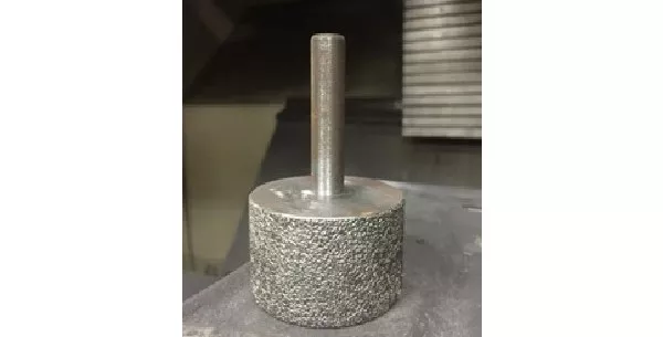
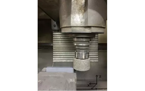
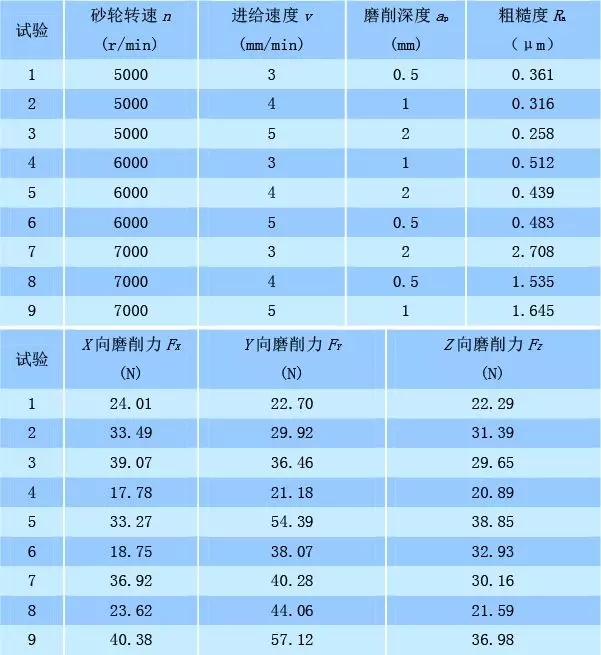
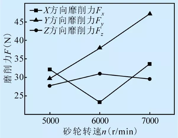
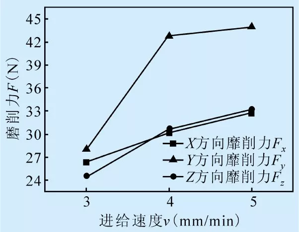
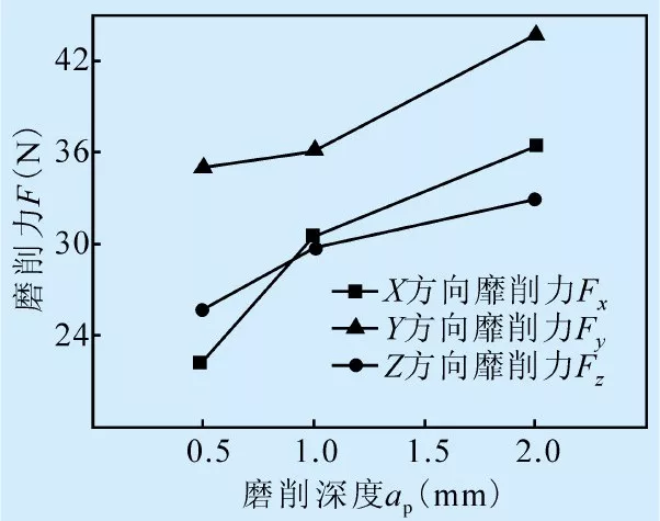
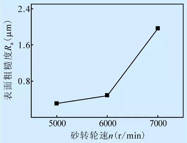
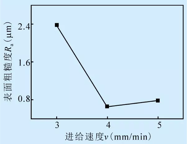
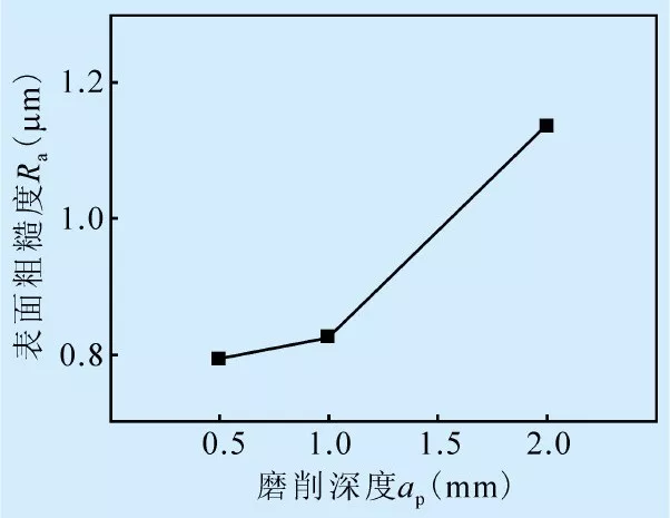
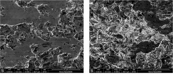
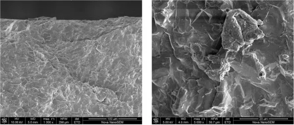
Silicon carbide (SiC) ceramic materials have excellent properties such as high hardness, high wear resistance, corrosion resistance, high temperature resistance, low density and good thermal conductivity. They are widely used in aerospace, machinery manufacturing, automotive parts and defense industry. At present, the use of diamond grinding wheel for grinding silicon carbide is a widely used processing method. Domestic grinding processing mainly carries out experimental research on small grinding depth, and the processing efficiency is low. Wang Jian et al. conducted an in-depth study on the sub-grinding surface damage detection method. The electroplated diamond grinding wheel was used to carry out the reaction-sintered silicon carbide grinding test with a feed rate of 100 mm/min and a grinding depth of 0.05 mm. The results show that the angle polishing method and the cross-section microscopic observation method can accurately and intuitively detect the subsurface damage of grinding. He Yong et al. studied the grinding force variation of single diamond grinding SiC, and the table speed is 25m. /min, the grinding depth is up to 40μm. The results show that the tip angle of the abrasive grain has a significant influence on the grinding force, and the grinding force increases with the increase of the angle. Yao Wang et al. used the diamond grinding wheel to react the sintered silicon carbide. Grinding research, the material removal mechanism is mainly for brittle fracture removal, and the local material removal method is plastic resection. In this paper, the orthogonal test of the face grinding of silicon carbide ceramics is carried out by using diamond grinding wheel. The experimental parameters are low feed rate and large grinding depth. The influence of different grinding parameters on the grinding force and the quality of the grinding surface is analyzed. The damage form of the ground surface is further verified by the removal mechanism of the silicon carbide ceramic grinding material, which has certain reference significance for the silicon carbide grinding process. 1 Test conditions The test machine is a BV75 vertical machining center. The main performance parameters are shown in Table 1. Table 1 BV75 vertical machining center performance parameters The test used a resin bond diamond grinding wheel (see Figure 1). The grinding wheel has a diameter of 60 mm, a width of 35 mm and a particle size of 80 mesh. The surface is ground by the end face of the grinding wheel, and the feed direction of the table is X negative direction (see Figure 2). The test material was reaction-sintered silicon carbide with a size of 96 mm × 56 mm × 15 mm, and the mechanical properties of the material are shown in Table 2. Table 2 Mechanical properties of silicon carbide The test mainly explores the change of grinding force during grinding and the influence of grinding wheel speed n, grinding wheel feed speed v, grinding depth ap on the surface quality of grinding. The level of orthogonal test factors is shown in Table 3. The results of the orthogonal grinding test of SiC ceramics are shown in Table 4. Figure 1 Diamond wheel Figure 2 Grinding schematic Table 3 SiC ceramic grinding orthogonal test factor level table Table 4 Orthogonal test visual analysis table 2 test results and analysis (1) Grinding force Figure 3a is a plot of the grinding force as a function of wheel speed. It can be seen from the figure that as the rotation speed of the grinding wheel increases, the overall change trend of the grinding force increases. This is because the surface grinding method is used. When the rotation speed is high, the preload of the grinding wheel handle affects the stability of the grinding wheel rotation. Larger, the end face of the grinding wheel fluctuates in the Z direction, resulting in an increase in the grinding force. Figures 3b and 3c show the grinding force as a function of feed rate and depth of grinding, respectively. As can be seen from the figure, the grinding force increases with the increase of the feed speed and the grinding depth. This is because when the feed speed and the grinding depth increase, the friction and wear of the abrasive grains on the silicon carbide material is enhanced. Therefore, the grinding force increases. Comparing Figures 3a, 3b and 3c, it can be seen that the grinding force in the Y direction is greater than the grinding forces in the other two directions. Analyze the cause of the grinding force in different directions. The velocity of a single abrasive at a certain moment can be decomposed into the velocity along the X direction and the velocity along the Y direction. The velocity in the X direction is equal to the feed velocity, and the velocity in the Y direction is equal to The line speed of this point. Because the feed rate used in the test is small, the grinding wheel rotates at a high speed, the Y-direction speed is much larger than the X-direction speed, and the Y-direction friction wear effect is stronger than the X-direction friction wear effect, so the Y-direction grinding force is greater than the X-direction grinding. force. The Z-direction grinding force is mainly generated by the vibration of the grinding wheel in the Z direction. Since the grinding wheel movement mode is mainly the feeding motion in the XY plane, the amplitude in the Z direction is small, so the grinding force is small. (a) (b) (c) Fig. 3 Curve of grinding force with grinding parameters (2) Surface roughness Figure 4a is a graph of surface roughness as a function of wheel speed. It can be seen from the figure that when the rotation speed is 7000r/min, the grinding surface roughness is much larger than 5000r/min and 6000r/min, the roughness increases with the increase of the grinding wheel rotation speed, and the grinding surface has a clear grinding wheel wear scar. . Because the test uses the grinding wheel end face grinding method, the pre-tightening force of the grinding wheel handle has a great influence on the rotation stability of the grinding wheel in the XY plane. When the rotation speed reaches 7000r/min, the high-speed rotation increases the instability of the grinding wheel, and the single grinding The longitudinal amplitude of the granules when grinding the surface friction material is large, so that the grinding wear of the surface grinding wheel particles is significantly increased, and the surface roughness is increased. Figure 4b is a plot of surface roughness as a function of feed rate. It can be seen from the figure that when the feed speed is 4mm/min and 5mm/min, the change of the surface roughness of the grinding conforms to the empirical rule and shows an increasing trend; when the feed speed is small, the feed speed has little effect on the roughness. Large feed rate can be selected to ensure the efficiency of grinding. When the feed rate is 3mm/min, the grinding surface roughness value is large. It can be seen from the test of the seventh group in Table 4 that the roughness is 2.708μm, which is due to the significant effect of the pre-tightening force of the grinding wheel at high rotation speed. The smoothness is reduced at high rotation speeds, and the longitudinal amplitude of a single abrasive grain increases when moving on the grinding surface, resulting in a large surface roughness. Figure 4c is a plot of surface roughness as a function of grinding depth. As can be seen from the figure, the grinding surface roughness increases as the grinding depth increases. When the feed rate is constant, when the grinding depth is increased, the material removal time per unit time is increased, and the material removal is insufficient, so that the residual stress of the grinding surface after the brittle fracture of the material increases, so the surface roughness increases. (a) (b) (c) Figure 4 Surface roughness curve with grinding parameters (3) Grinding damage Figure 5 is a grinding surface magnified 5000 times with a scanning electron microscope, and different types of ground surface features can be observed. Both Fig. 5a and Fig. 5b have large brittle fractures, indicating that the material removal form of the SiC ceramic material grinding process is mainly brittle fracture removal. It can be observed from Fig. 5a that the material "cladding" phenomenon occurs due to the heat of grinding, on which the scratches left by the abrasive grains of the grinding wheel, and the darker black areas are the original hole defects inherent in the material. Cracks generated during the grinding process can be observed from Figure 5b. Observing the upper edge of the side surface perpendicular to the grinding surface, there is a visible "cracking" damage visible to the naked eye. "Bumping" is a common damage in ceramic processing, mainly because cracks extend to the edge of the material during the grinding process, resulting in material breakage. Figure 6 is a microscopic topography of the material "crashing" damage. It can be seen from the figure that the essence of the "crashing" damage is the blockage of the material; Figure 6b is the microscopic morphology of the "cracking" damage of silicon carbide. It can be seen that the "crashing" damage is also due to the material. Caused by the removal of brittle fracture. (a) (b) Figure 5 Micro-morphology of the grinding surface (5000×) (a) (b) Figure 6 "Clashing" damage microscopic morphology In the grinding of silicon carbide ceramic materials, the main form of material removal is brittle removal. Lateral cracks and radial cracks occur when the average abrasive load of the material exceeds its critical cutting load. As the transverse crack propagates, the material undergoes brittle fracture and is eventually removed in the form of massive exfoliation. Material removal is also accompanied by plastic deformation during the grinding process. This is because during the grinding process, the abrasive grains and the material are strongly rubbed and squeezed, and a large amount of heat is generated. When the average load of the abrasive grains is lower than the critical cutting load of the silicon carbide, the material will be plastically deformed. summary Based on the existing research, the orthogonal experiment of grinding silicon carbide with large grinding depth is carried out to further verify the removal mechanism of grinding materials, and the grinding parameters and grinding surface roughness of different grinding parameters are explored. influences. The results showed that: (1) When the diamond wheel grinds the silicon carbide ceramic, the material removal form is mainly the brittle fracture removal of the material caused by the crack propagation. When the grinding load is less than the critical cutting load of the material, the material will be plastically deformed. (2) The damage forms of the grinding surface mainly include radial cracks, transverse cracks and high temperature cladding; the side of the vertical grinding surface will have "cracking" damage. (3) When using small feed speed and large grinding depth grinding, when the grinding wheel rotates at a large speed, the pre-tightening force of the grinding wheel has a significant influence on the grinding force and the roughness of the grinding surface. Under the condition of high rotation speed, The effect of the preload is greater than the effect of the wheel speed and feed rate. (4) Large grinding depth can obtain better grinding surface quality. Comparing the influence of different parameters on the grinding results, the grinding surface quality is best when the grinding wheel speed is 5000r/min, the feed speed is 5mm/min, and the grinding depth is 2mm. A Jaw Crusher is one of the main types of primary crushers in a mine or ore processing plant. The size of a jaw crusher is designated by the rectangular or square opening at the top of the jaws (feed opening). Primary jaw crushers are typically of the square opening design, and secondary jaw crushers are of the rectangular opening design. However, there are many exceptions to this general rule. Jaw Crusher Jaw Crusher,Mini Jaw Crusher,Portable Jaw Crusher,Mobile Primary Jaw Crusher Shenyang Sanland Mining Equipment Manufacture Co., Ltd. , https://www.sanlandcrusher.com


A Jaw Crusher reduces large size rocks or ore by placing the rock into compression. A fixed jaw, mounted in a "V" alignment is the stationary breaking surface, while the movable jaw exerts force on the rock by forcing it against the stationary plate. The space at the bottom of the "V" aligned jaw plates is the crusher product size gap, or the size of the crushed product from the jaw crusher. The rock remains in the jaws until it is small enough to pass through the gap at the bottom of the jaws.