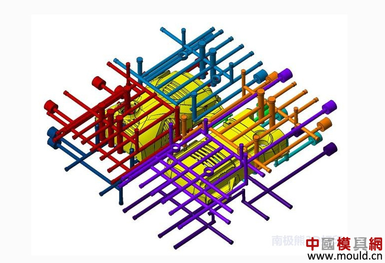
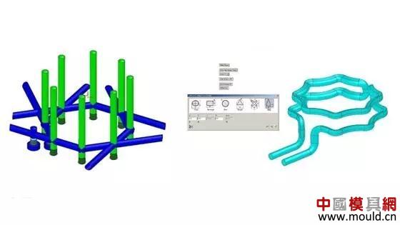
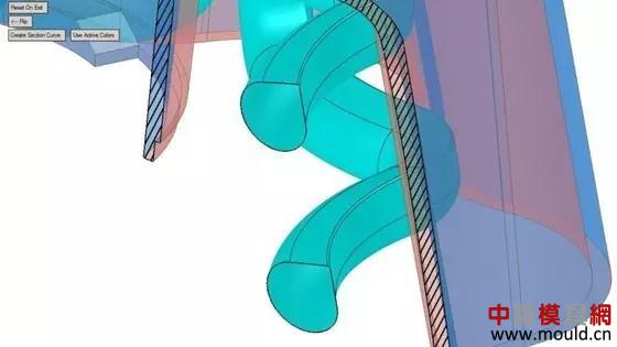
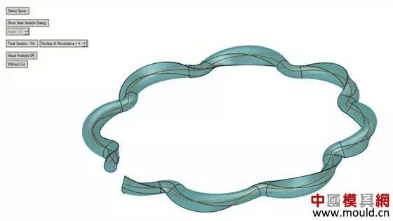
One of the hot topics in the field of 3D printing is the cooling water circuit manufacturing of injection molds. The 3D printing technology avoids the limitation of cross-drilling in the manufacture of the cooling water circuit. The conformal cooling water circuit can also carry out different cooling circuit designs according to the cooling requirements so as to dissipate heat at a uniform speed to promote the uniformity of heat dissipation. In some mold manufacturers, the cooling mold business has accounted for 40% of the total business. So, what is the difference between the design principle of 3D printing conformal cooling water circuit and the traditional cooling water circuit? What can be learned from the design and manufacture of traditional cooling waterways? The following points of design experience shared by the mold additive manufacturing experts will give some inspiration to these issues. The diameter of the waterway. Conventional cooling water circuits made using drilled holes are typically 7/16 inch (approximately 11.11 mm) in diameter. Cooling circuits made in this way, if they are too large in diameter, may cause the waterway to be inaccessible to the mold surface while avoiding the mold parts. If the diameter is too small, bit drift may occur during water processing. Although additive manufacturing techniques circumvent some of the limitations of drilling methods, the design of waterways still requires that the diameters be set within a common range of dimensions that have been empirically verified, thereby reducing the uncertainty of this technique. The left picture above shows the cooling water circuit processed by the traditional drilling method, and the right picture shows the cooling water channel. The cooling time of the traditional cooling waterway is 50.89 seconds, and the cooling water cooling time of the cooling water is 44.97 seconds, a decrease of 12%. Cross-sectional area. When the cooling waterway is processed by drilling, the cross-sectional area of ​​the waterway remains constant. Although 3D printing technology can produce a waterway with many different shapes, the 3D printing conformal cooling waterway should keep the cross-sectional area of ​​the waterway constant, thus ensuring a constant volume of cooling liquid through the waterway. The upper section of the figure is a teardrop shaped cooling water circuit. The inlet and outlet diameters are 7/16 inches (about 11.11 mm), and the teardrop shaped waterway cross-sectional area needs to be consistent at design time. In this case, the perimeter of the teardrop shaped waterway is 1.574 inches (about 39.93 mm), and the circumference of a traditional circular waterway of the same area is 1.374 inches (about 34.90 mm). The cooling water circuit has a larger surface area to carry the heat away from the mold. The distance from the mold surface. There is no fixed rule for the distance between the cooling water circuit and the mold surface. For example, some companies keep the distance in the design exactly equal to the distance of the water path diameter, and some companies reserve the distance of 2 times the water path diameter. For most conformal cooling circuits, the distance to the mold surface depends on the geometry of the part. When designing the distance from the mold surface, there is a principle that should be followed in order to maintain the same distance between the follow-up waterway and the mold surface, so as to achieve a uniform cooling effect. The length of the cooling waterway. When using the drilling method to process the cooling water circuit, if the debris generated during drilling is not emptied, bit drift or damage may occur. In this case, people will choose to keep the cooling water circuit design as short as possible. Although the use of 3D printing technology to produce the shape of the cooling water channel, there is no problem such as cutter damage, but it is still not recommended in the design of the waterway design is too long. This is due to the fact that the cooling water can enter and exit more rapidly in the shorter cooling water circuit, making the heat distribution more uniform. Another rule of cross-sectional area. Because many short cooling water circuits can be cooled more evenly, some conforming cooling water circuits are designed according to the idea of ​​capillary tubes. That is, a large cooling water circuit is divided into multiple small and short waterways, and then Import a large waterway. In this case, the sum of the cross-sectional areas of the multiple small waterways should be equal to the cross-sectional area of ​​the inlet and outlet of the large waterway, so as to ensure the uniform flow of water and further reduce the risk of warpage. Rotary structure. The amount of water in the mold cooling water circuit is a factor that affects the cooling time of the mold. The larger the water volume, the shorter the cooling cycle time. Another influencing factor is water turbulence. Although the inner surface of the 3D printing profile cooling water circuit is not polished, some turbulence is generated, but more turbulence can be generated if the rotating structure is added at the time of design. For example, the cooling water circuit shown in FIG. 3 adds four rotation structures to the top circuit at the time of design. These design rules are not all the rules that need to be paid attention to in the successful 3D printing of the conformal cooling water circuit. When the mold making user designs the 3D printing follow-up cooling water circuit, he should have a systematic understanding of the injection mold manufacturing. There are many lessons to be learned from the traditional mold cooling water circuit design principles. These experiences are the basis for the effective design of 3D printing conformal cooling water circuits. Narcotic Safety Cabinets,Chemical Storage Cabinets,Types Of Chemical Storage Cabinets,Chemical Storage Cabinet Wuxi Huanawell Metal Manufacturing Co., Ltd. , https://www.wxhnwmetal.com


