Air Cooler Fan,Fan Cooler,Portable Cooling Fan,Cooling Fan For Bedroom Ningbo Glory King Imp&Exp Co., Ltd. , https://www.gloryelectrical.com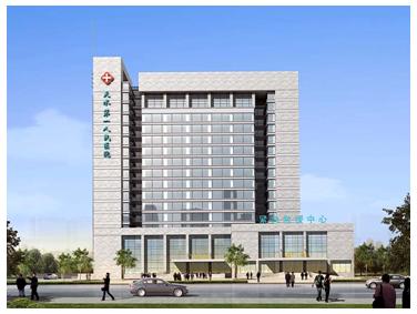
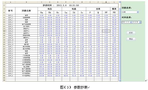
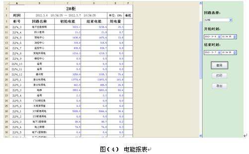
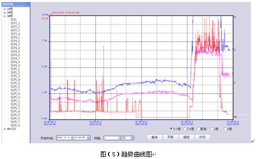
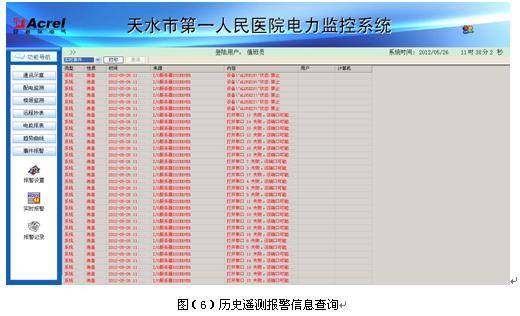
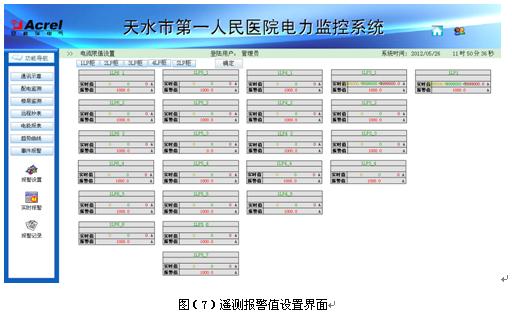
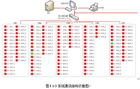
0 Overview The Acrel-2000 power monitoring system makes full use of the latest developments in modern electronic technology, computer technology, network technology and fieldbus technology to perform distributed data collection and centralized monitoring and management of variable power distribution systems. The secondary equipment of the power distribution system is networked, and the field devices of the distributed power distribution stations are connected as an organic whole through the computer and the communication network to realize remote monitoring and centralized management of the power grid operation. The remote meter reading system can display all the collected data in real time and save it in the database. Therefore, all real-time and historical electrical parameter data of each loop can be manually queried and presented to the user in the form of a table for printing, save. As shown in Figure 3. The active energy data collected by the energy report system automatically generates daily report, monthly report and annual report according to different circuit names, and has a report printing function, and can query the power consumption in a certain period of time of a certain loop. With printing, these reports can also be exported in Excel format. As shown in Figure 4. In the trend curve load trend curve interface, you can visually check the load operation of the loop. View real-time and historical trend curves, click the corresponding button or menu item on the screen to complete the corresponding function switching; help users to enter the trend analysis and fault recall, with curve printing function. Provides intuitive and convenient software support for analyzing the health of the entire system. See picture (5). The event record and alarm telemetry alarm function mainly completes the monitoring of the load incoming line of the low-voltage outlet circuits. The over-limit pop-up alarm interface indicates the specific alarm position and audible alarm, reminding the on-duty personnel to deal with it in time. The telemetry alarm value setting interface can see the real-time value and alarm setting value of each monitoring point, which is convenient for the on-duty personnel to compare the incoming line settings. The load limit value can be freely set under the corresponding authority. With historical query function. See Figure (6) and Figure (7). The communication diagram shows the communication structure of the system, mainly showing the networking structure of the system. The system adopts a layered distributed structure and monitors the communication status of the interval layer devices. Red indicates normal communication and green indicates communication failure. See picture (8). 4 Conclusion With the development of intelligent buildings and the wide application of electric power, the intelligent integrated management of the intelligent building's power distribution system has become an inevitable trend of the national office building and the construction of large-scale public buildings. The paper is based on Acrel-2000. The power monitoring system can not only monitor the power running status and abnormal power consumption in real time, but also analyze and process the data, display it in a user-applicable manner, meet the user's needs, and realize the analysis and processing of the collected data. Electrical energy reports, analysis curves, graphics, etc., greatly facilitate the use of users, facilitate real-time monitoring of power distribution systems and remote meter reading and analysis of electrical parameters, and provide reference for energy-saving technologies of intelligent buildings.
1 Project Introduction The First People's Hospital of Tianshui City, Gansu Province was founded in 1950. It covers an area of ​​98 acres and has 1,045 beds. It is the only third-grade hospital in Tianshui City and the largest medical center in the city. A comprehensive hospital integrating teaching, research and prevention. It is a "baby-friendly hospital" jointly named by the Ministry of Health, UNICEF, and the World Health Organization. It is a health care center in Tianshui and southeastern Yunnan, and a critically ill treatment center. The hospital has an annual outpatient diagnosis and treatment of 360,000 person-times, and more than 17,000 inpatients are admitted to the hospital each year. 6,000 person-times of large and medium-sized operations are carried out, and more than 3,000 critically ill patients are rescued annually.
The hospital has strong technical force and has 698 employees, including 21 seniors, 73 associate professors and 303 intermediate titles. They enjoy special government allowances and 6 provincial and ministerial labor models. More than 30 hospitals have been evaluated. Provincial and municipal management top talents, including 3 provincial academic leaders, 30 "222" innovative talents at the municipal level, 1 national advanced health system worker, 1 national "three eight red flag bearers", Gansu province "May 4 "One youth medal, three model workers in the city, two outstanding young people in the city, and six people have gone to Israel, Singapore, Australia, and Madagascar to perform internationalist medical assistance tasks. The minimum degree of hospital clinicians is undergraduate, and all clinical departments are presided over by senior professional technicians, which ensures that the hospital's admission and diagnosis rate is over 95%, the critical patient's rescue success rate is over 95%, and the nursing technology operation qualification rate is up to 98% or more.
The waiting room of the original outpatient building of Tianshui First People's Hospital is small, the treatment process is not smooth, which seriously restricts the development of the hospital. For sustainable development, it invests 150 million yuan to build a new emergency door building with a total construction area of ​​45,340 square meters. The 20th floor is integrated with outpatient, emergency, ward and underground parking.
This project is the power monitoring system of the first emergency department building of Tianshui First People's Hospital. There are two systems and two floors. The project monitors the power distribution of these two power distribution systems. The monitoring scope is T1 and T2 of underground substation. The low-voltage inlet cabinets, the communication cabinets, the feeder cabinet instruments of the T3 and T4 transformers and the instruments in the distribution cabinets in each floor are monitored.
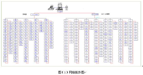
2 System structure description The system has a total of 328 instruments (including ACR network intelligent power meter, ADL network multi-function meter PZ three-phase energy meter, PZ three-phase current meter,), divided into 13 buses, due to substation and duty room The distance is relatively close, so the shielded twisted pair cable is directly connected, and finally the cable is connected to the electrician duty room to connect to the monitoring host to realize the data connection between the meter on the bus and the monitoring host.
The monitoring system adopts a layered and distributed structure, that is, the field device layer, the network communication layer and the station control management layer; as shown in Figure (1):
1) The field equipment layer is mainly: multi-function network power meter, switch quantity, analog quantity acquisition module and intelligent circuit breaker. These devices are respectively installed in the electrical cabinet corresponding to the corresponding primary equipment. These devices all adopt RS485 communication interface, and realize on-site data collection through the on-site MODBUS bus networking communication.
2) The network communication layer is mainly: communication server, whose main function is to collect the scattered devices in the field, and transfer them to the station control layer at the same time to complete the data interaction between the field layer and the station control layer.
3) Station control management: equipped with high-performance industrial computers, monitors, UPS power supplies, printers, alarm buzzers and other equipment. The monitoring system is installed on the computer to collect and display the running status of the field device and display it to the user in the form of human-computer interaction.
The above network instruments adopt RS485 interface and MODBUS-RTU communication protocol, RS485 adopts shielded line transmission, generally adopts two connections, the wiring is simple and convenient; the communication interface is half-duplex communication, that is, both sides of the communication can receive and send data but Only data can be sent or received at the same time, and the maximum data transmission rate is 10Mbps.
The RS485 interface is a combination of balanced driver and differential receiver. It has enhanced noise immunity and allows up to 32 devices to be connected on the bus. The maximum transmission distance is 1.2km.
3 Main functions of power monitoring system 3.1 Data acquisition and processing Data acquisition is the basis of power distribution monitoring. Data acquisition is mainly completed by the underlying multi-function network instrument, realizing local real-time display of remote data. The signals that need to be collected include: three-phase voltage U, three-phase current I, frequency Hz, power P, power factor COSφ, electrical EPI, and remote device operating status.
The data processing mainly displays the electric parameters collected as required in real time to the user, and achieves the automation and intelligent requirements of the power distribution monitoring, and simultaneously stores the collected data into the database for the user to inquire.
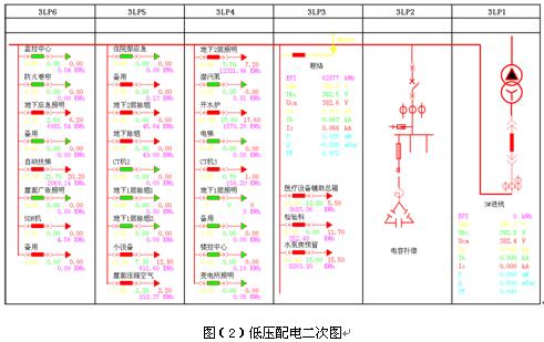
3.2 Human-computer interaction system provides a simple, easy-to-use, and good user interface. Using the full Chinese interface, the CAD graphic shows the electrical main wiring diagram of the low-voltage power distribution system, showing the status of the power distribution system equipment and the corresponding real-time operating parameters, the screen timing wheel patrol switching; the screen real-time dynamic refresh; analog quantity display; switch quantity display; continuous Record display, etc.
3.3 The diachronic event diachronic event viewing interface is mainly for the user to view the fault records, signal records, operation records, and over-limit records that have been made to provide convenient and friendly human-computer interaction. Through the historical event viewing platform, you can customize the requirements according to your own requirements and query conditions. It is convenient to locate the historical events you want to view, and provide good software support for your operation of the entire system.
3.4 Database establishment and query mainly complete remote measurement and remote signal collection, and establish a database to generate reports for users to query and print.
3.5 User Rights Management For different levels of users, set different permission groups to prevent the loss of production and life caused by human error, and realize the safe and reliable operation of the power distribution system. Users can log in, log out, change passwords, add deletes, etc. through user management, which is convenient for users to modify accounts and permissions.
3.6 Operation load curve The load trend curve function is mainly responsible for timing the incoming line and important loop current and power load parameters, and automatically generating the running load trend curve, so that users can know the running load status of the equipment in time. Click the corresponding button or menu item to complete the corresponding function switching; you can view the real-time trend curve or historical trend line; you can perform translation, zoom, range conversion and other operations on the selected curve to help users enter the line trend analysis and fault recall. Analysis of the health of the entire system provides intuitive and convenient software support.
3.7 Remote Report Query The main function of the report management program is to design the report style according to the needs of the user, and filter the data processed in the system to generate the report data required by the user. The program can also use the timed save, print or summon save and print mode for the report file according to the user's needs. At the same time, the program also provides users with the function of generating report file management.
The report has the function of freely setting the query time to realize the energy statistics, data export and report printing of day, month and year.
The data acquisition and system diagram shows that the incoming circuit uses the ACR330ELH multi-function harmonic meter, which is a network power meter designed for power monitoring needs of power systems, industrial and mining enterprises, public facilities, and intelligent buildings. It can measure all conventional power parameters. Such as: three-phase voltage, current, active power, reactive power, power factor, frequency, active power, reactive power, and can monitor the voltage, current 2-131 harmonic components and other electrical parameters. And the instrument has 4 photoelectric isolation switch input contacts and 2 relay control output contacts, these contacts can be used with the intelligent circuit breaker to realize the remote signaling and remote operation of the circuit breaker. This series of network power meters are mainly used in substation automation, distribution network automation, residential power monitoring, industrial automation, energy management systems and intelligent buildings.
The distribution circuit mainly adopts PZ80-E4 three-phase electric energy meter, which mainly measures all conventional power parameters, such as: three-phase voltage, current, active power, reactive power, power factor, frequency, active energy, reactive power degree.
The secondary diagram of low-voltage power distribution is shown in Figure (2). The function has electric power telemetry. It mainly monitors the electrical parameters of the running equipment, including: line three-phase voltage, current, power, power factor, electric energy, frequency and other electrical parameters and the distribution loop. Three-phase current; the remote signal function realizes the operation status of the field device, including: the switch's branching and closing operation status and communication fault alarm; when the circuit breaker is displaced, an alarm signal will be sent to remind the user to handle the fault in time.