Custom Trophies,Metal Crafts Champion Trophy,Competition Award Trophy,Gold Plated Championship Trophy Topwell Crafts Co., Ltd , https://www.topwellmetal.com
Key words: Ultrasonic flowmeter Doppler time difference coupling agent Ultrasonic flowmeter is a kind of velocity type flowmeter which uses the ultrasonic pulse to measure the fluid flow. It entered the industrial production and measurement field in China since the 1980s, and The 1990s have grown rapidly. In recent years, with the development of electronic technology and digital technology, the ultrasonic flowmeter technology has been continuously developed. Based on different principles and different structures, various types of ultrasonic flowmeters suitable for different occasions have been widely used, especially in measuring certain Because of its advantages such as stable operation, simple installation, and small maintenance, these special medium fluids are favored by users. Therefore, they have been obtained at domestic and foreign oil, chemical, metallurgy, tap water, mining, paper, steel and other industrial and mining enterprises. A wide range of applications. There are nine units in a combined atmospheric and vacuum installation that are in important positions.
1 Classification of Ultrasonic Flowmeters Ultrasonic flowmeters are meters that measure the volume of a full tube using changes in the speed of propagation of ultrasound beams in a fluid. According to different measurement principles, structures, power supply modes and usage scenarios, there are several forms.
According to the principle of signal detection can be divided into a variety of different, mainly sometimes poor, Doppler and sound beam deflection type flowmeter. The sonic beam drift type flow meter uses the degree of deflection generated by the fluid flow when the ultrasonic wave propagates in the fluid to reflect the flow rate or flow value.
According to the different configurations of ultrasonic transducers, it can be divided into three types: single-channel, dual-channel and multi-channel flowmeters. The two-channel transducer can emit two independent ultrasonic signals with different frequencies. The two frequencies are used to automatically identify and eliminate noise interferences such as those caused by unstable frequency excitation, thereby greatly improving measurement accuracy.
According to the different power supply modes of the transducer, it can be divided into three types: outer post type, pipe segment type and insert type. The pipe segment type ultrasonic flowmeter integrates the transducer and the measuring tube, and solves the problem that the pipeline causes serious fouling of the ultrasonic signal due to the loosening of the inner wall of the material and the like, and at the same time, improves the measurement accuracy. The plug-in ultrasonic flowmeter can use a special tool to drill a hole in the pipe under continuous flow, and insert the transducer into the pipe for measurement. Since the transducer emits and receives signals directly in the pipeline, its signal passes through only the measured medium without passing through the wall and the lining, so the flow measurement is not affected by the material of the tube wall and the lining.
According to different occasions of ultrasonic flowmeters, they can be divided into two types, fixed and portable. The fixed ultrasonic flowmeter is installed in the pipeline at a fixed position for long-term continuous operation, usually with 4~20mA signal output for remote display and control. The portable flowmeter is mainly used for making temporary measurements of fluid flow in pipes of different calibers and materials, displaying or storing flow information locally.
2 Ultrasonic Flowmeter Measurement Principle 2.1 Doppler Ultrasonic Flowmeter The Doppler ultrasonic flowmeter uses the Doppler effect principle to measure three-dimensional flow.
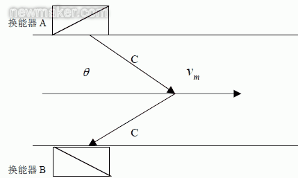
As shown in Fig. 1, transducer A transmits an ultrasonic signal with a frequency of fA. After passing through the suspended particles or bubbles in the fluid in the pipeline, the frequency shifts to reflect the frequency of fB to transducer B. Lehrer effect, the difference between fA and fB is the Doppler frequency difference fd.
Let the average flow velocity of the fluid be vm, the ultrasonic velocity of sound be C, and the Doppler frequency shift fd be proportional to the average velocity vm of the fluid, ie ![]()
![]()

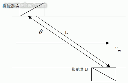
As shown in Figure 2, ultrasonic transducers A and B are mounted on the outside of the measuring tube to form a measurement channel, the distance between the two transducers is L, and the measurement channels A and B are formed with the central axis of the measurement pipeline. Inclusion angle θ, ultrasonic wave propagation velocity in the measured fluid is C.
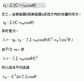
The ultrasonic signal is transmitted from transducer A to transducer B. This is the direction of the forward flow and its propagation time is: 

FIC115 measures electric refinement of normal first-line oil flow;
FI134 measurement to refine the normal first-line oil flow;
FI135 measures the bottom oil flow of atmospheric distillation tower;
FI137 measures the top oil flow in the mid-pressure tower;
FC1209 measures desalination all the way to the oil flow;
FC1209A measures the desalination of the second road oil flow;
FC1210 measures desalination three-way oil flow;
FC1214A measures the first-line oil flow in the vacuum distillation tower;
FC1214B measures the second-line oil flow in the vacuum distillation tower.
The ultrasonic flowmeter used in this device measures fluids that are liquid (crude oil), and the fluid is relatively clean, with a low density and a relatively low viscosity of 0.6 to 0.9. Flow meters use time-differential measurement principles. The fault phenomenon that FIC115 often appears is: Sometimes the fluctuation is relatively large and it automatically returns to normal after a period of time. The failure of FI1209A is that the measured value is very small and deviates from the actual value for a long period of time, and the measured value hardly changes.
4 ultrasonic flowmeter failure analysis and judgment and processing For ultrasonic flowmeter FIC115 failure, go to the scene to see, there is no alarm display information, view the speed setting value of 800, and the design value, and then view the ultrasonic signal strength is 58.6, also Normally, no loosening was observed between the signal line and the power cable. Usually normal measurement, sometimes a short time of large fluctuations, may be a short-term ultrasonic processor core processor system failure, processing, however, this possibility is relatively small; most likely a process reason, the short pipeline of crude oil The phenomenon of dissatisfaction with the tube in time leads to the occurrence of gas-liquid two-phase conditions, which causes the propagation speed of the ultrasonic wave to change and the measurement to fluctuate greatly. It is also possible that there are solid particles, fouling or corrosion of the pipe in the pipe. After careful inspection, it was found that the transducer was installed at the highest point of the pipeline, so that the phenomenon of flow breaking in the pipeline could easily occur. As long as the instantaneous interruption of the upstream flow occurred, it would inevitably lead to a break in the transducer, if the transducer were to be Installed at the lower end of the highest point, the instantaneous flow breaks in the upstream, and the position of the transducer is relatively low. Due to gravity, the flow-breaking phenomenon will not occur immediately. So the FIC 115 should be too high for the transducer to be installed, as long as its position is moved to a lower place, the current fault will be solved.
For the failure of FI1209A, check the sound speed setting value is 900. Just like the design value, check the ultrasonic signal strength is 38.7. Compared with other ultrasonic flowmeters, the number of other units is about 60, so we will The coupling agent is added between the transmitter and the lining of the transducer to enhance the reception of the ultrasonic signal and increase the signal intensity of the ultrasonic wave. Due to the limitation of on-site installation conditions, the other end of the transducer could not be removed, tightly attached to the heat-insulating wall of the heat exchanger, so only one of the transducer's couplants was added, and the ultrasonic intensity was increased to 42.4, which was not eliminated. malfunction. It is not that the medium density has changed, so the original medium density setting value is changed, and after several changes, the measurement result is found to be incorrect. Check the installation situation of the field transducer, there is no loose phenomenon, the instrument wiring is normal. Suspected that the core processor circuit board of the ultrasonic flowmeter is faulty, the two signal lines of the ultrasonic flowmeter FI1209A are removed and connected to the ultrasonic flowmeter FI1209 next to it. The indicator value is almost the same as the FI1209, so the ultrasonic flowmeter The circuit board is good. Contact the manufacturer, said that the ultrasonic signal strength can not be less than 45, the original is the coupling agent dry, affecting the transducer on the ultrasonic signal transmission and reception, resulting in ultrasonic signal strength is not enough, so the measurement can not be normal.
5 Concluding remarks Through further understanding of the principle of ultrasonic flowmeters and analysis and judgment of on-site ultrasonic flowmeter failures, some insights have been drawn. The unreasonable installation of transducers is the main reason why ultrasonic flowmeters cannot work properly. The installation of the transducer requires consideration of both the choice of the mode and the determination of the position. In terms of installation methods, transducers for time-difference ultrasonic flowmeters mainly include W-type, V-type, Z-type, and X-type transducers. According to different pipe diameter and fluid characteristics to choose the installation method, usually W type for small diameter (25 ~ 75mm), V type for the middle diameter (25 ~ 250mm), Z type for large diameter (250mm or more ), X type is suitable for occasions where the measurement accuracy of the middle diameter (25-250mm) is high. In short, in order to improve the accuracy and sensitivity of the measurement, an appropriate installation method is selected so that the measurement signal (ie, the difference) matches the secondary instrument. At present, except for FI137, V-type installation (diameter 75mm) is used, and the rest are Z-type installations. In order to ensure the measurement accuracy of the instrument, the location of the site that meets certain conditions should be selected: usually, the upstream 10D and the downstream 5D straight pipe sections are selected; in the upstream 30D, the disturbance devices such as pumps and valves cannot be installed. Special attention should be paid to the fact that the transducer avoids contaminated power sources such as inverters and welding machines. The transducer should not be installed at the highest point of the pipeline to ensure that the pipeline is full of fluid. The transducer should be installed at a suitable space for easy maintenance or for disassembly when adding a coupling agent. In terms of maintenance: regularly check the signal and power cord, and periodically add a coupling agent to ensure the intensity of ultrasonic signal transmission and reception. In addition, a portable ultrasonic flowmeter is recommended to facilitate the judgment and handling of faults due to process reasons.
References [1] Zhu Bingxing, Wang Sen. Instrumentation Problem Set (Second Edition) [M]. Beijing: Chemical Industry Press, 2002, 7.
[2] Shi Xuan, Wang Danjun. Instrument maintenance workers [M]. Beijing: Chemical Industry Press, 2005.
Abstract: The continuous development of ultrasonic flowmeter technology and its advantages make it widely used. There are nine units in a combined atmospheric and vacuum installation that are in important positions. In this paper, the principle of measurement of Doppler and time difference ultrasonic flowmeters is introduced in detail, combined with the failure of the device in the use of ultrasonic flowmeters, analysis and judgment processing. Finally, give opinions on the installation and maintenance of ultrasonic flowmeters. So the fluid velocity When the pipeline condition, transducer installation position, transmission frequency, and sound velocity are determined, C, fA, and θ are constants. The average flow velocity of the fluid is directly proportional to the Doppler frequency shift, and the fluid velocity can be obtained by measuring the frequency shift. Get fluid flow. Fig.1 Measurement principle of Doppler ultrasonic flowmeter 2.2 Time difference ultrasonic flowmeter content When the ultrasonic wave propagates in the fluid, the ultrasonic pulse emitted by the probe A is received by the probe B. At the same time, the probe B also transmits the ultrasonic pulse and is received by the probe A. Therefore, the same propagation distance produces the time difference between the forward and countercurrent propagation. The time-difference type ultrasonic flowmeter uses the principle that the time difference between ultrasonic forward and countercurrent propagation is proportional to the fluid flow rate to obtain the flow rate, and then the flow rate is obtained. In the equation, C, L, and θ are all constants, and the average flow velocity vm can be obtained by measuring the time difference Δt. The volumetric flow rate of the fluid can be calculated by multiplying the cross-sectional area of ​​the pipe.
Figure 2 Time Difference Ultrasonic Flowmeter Working Principle
3Usage of ultrasonic flowmeters on devices and their failures A total of nine ultrasonic flowmeters have been used in conjunction with a combined atmospheric and vacuum unit: