This paper summarizes the defects of Stamping Parts in the stamping factory, analyzes the causes and provides preventive measures. The content is the essence of practical production experience, recommended intensive reading. 1. Produce stamping waste 1) Reason: Inferior quality of raw materials; Improper installation and use of the die; The operator does not feed the strips correctly along the positioning or does not guarantee that the strips are fed at a certain gap; Due to long-term use, the die has a gap change or wear of its own working parts and guiding parts; The dies are relatively loose due to the impact vibration time and the loose parts of the fastening parts cause relative changes in the mounting positions of the dies; The operator's negligence did not operate according to the operating procedures. 2) Countermeasures: The raw materials must conform to the specified technical conditions (strictly check the specifications and grades of the raw materials, and test the workpieces with high dimensional accuracy and surface quality requirements under conditions). Strict compliance with all aspects specified in the process specification; The working equipment such as presses and dies used shall be guaranteed to work under normal working conditions; A strict inspection system is established in the production process. The first part of the stamping parts must be inspected comprehensively. Only after the inspection is passed can the production be put into production. At the same time, the inspections should be strengthened. When accidents occur, they should be dealt with in time. > The leading edge CNC technology WeChat is good, remember to pay attention. Adhere to the civilized production system, such as the transfer of workpieces and blanks must use the appropriate station equipment, otherwise it will crush and scratch the surface of the workpiece to affect the surface quality of the workpiece; In the stamping process, the inside of the mold cavity should be cleaned, and the workpieces that have been arranged in the work place should be placed neatly. 2. Blanking burrs 1) Reason: The punching gap is too large, too small or uneven; The cutting edge of the working part of the die becomes dull; The punch and the die are changed due to long-term vibration shock, and the center lines are not changed, and the axes do not coincide, resulting in a single-sided burr. 2) Countermeasures: Ensure the machining accuracy and assembly quality of the convex and concave molds, ensure the verticality of the punch and the side pressure and the entire die must have sufficient rigidity; When installing the punch, it is necessary to ensure the correct clearance of the male and female molds and make the convex and concave molds securely mounted on the mold fixing plate, and the end faces of the upper and lower molds should be parallel to the work surface of the press; The rigidity of the press is required to be good, the elastic deformation is small, the accuracy of the track and the parallelism of the pad and the slider are required to be high; Require the press to have sufficient punching force; Punching section shearing section allows height of burr Blanking plate thickness>0.3>0.3-0.5>0.5-1.0>1.0-1.5>1.5-2.0 New test mode burr height ≤0.015≤0.02≤0.03≤0.04≤0.05 The allowable burr height during production ≤0.05≤0.08≤0.10≤0.13≤0.15 3. The punching parts are warped and deformed 1) Reason: There are gap forces and reaction forces that do not generate torque on a line. (When the convex-concave gap is too large and the die edge has a reverse taper, or the contact area between the ejector and the workpiece is too small, warpage is generated). 2) Countermeasures: The punching clearance should be chosen reasonably; In the mold structure, the pressure plate (or pallet plate) should be increased in plane contact with the pressure plate and have a certain pressure; Check the die edge if it is found to have a reverse taper, the die edge must be trimmed properly; If the shape of the blanking part is complicated and the shearing force is not uniform, the pressing force is increased, and the stripping material is pressed before punching or punched with a high-precision press; The plate should be leveled before punching. If the warpage is still not eliminated, the punched workpiece can be leveled again through the leveling die; The material in the mold cavity is regularly removed, the surface of the thin plate material is lubricated, and a gas passage hole is arranged on the mold structure. 4. The outer edge of the blank and the accuracy of the inner hole are reduced in size. 1) Reason: Positioning pin, stopper pin, etc. change or wear too much; The operator's negligence is about to shift left and right when feeding. The dimensional accuracy of the strip is lower than the narrow and wide, and the feeding difficulty is difficult to be sent to the designated place. The strip will be offset in the guide plate and the inner hole of the workpiece which is punched out will have a large deviation from the front and rear positions of the shape. 5. When the part is bent, the size and shape are unqualified 1) Reason: The rebound of the material caused the product to fail; The positioner is deformed by wear and the strip is not positioned correctly, and a new positioner must be replaced; In the unguided bending die, when the press is adjusted on the press, the position of the bottom dead center of the press slider is improperly adjusted, and the shape and size of the bent piece are also unqualified; If the die pressing device of the mold fails or does not work at all, it is necessary to re-adjust the pressing force or replace the pressure spring to make it work normally. 2) Measures to reduce rebound: Selecting a stamping material with a stable mechanical modulus and a small yield point and a relatively stable mechanical property; Add a correction process, using a correction bend instead of a free bend; Before bending, the material is annealed, and the cold work hardening material is softened before being bent and formed; If the shape deformation occurs during the stamping process and it is difficult to eliminate; the slope of the punch and the die should be replaced or trimmed, and the gap between the punch and the die should be equal to the minimum material thickness; Increasing the contact area between the die and the workpiece, and reducing the contact area between the punch and the workpiece; Use the "overkill" approach to reduce the impact of rebound. 6. Cracks in the bent part of the bent part 1) Countermeasures: Eliminate the burrs on the outside of the bending zone, the burrs will cause stress concentration in the area, reduce the amount of bending deformation; remove the burrs in this area; The burr side is placed on the inside of the bending zone; When bending the workpiece, it is preferable to make the bending direction perpendicular to the fiber direction (rolling direction) of the material; The bending radius should not be too small, and the radius of the fillet should be increased as much as possible if the quality allows; The surface of the curved blank should be smooth and free of obvious protrusions and scars; An intermediate annealing process is used during bending to eliminate internal stress, and cracks are rarely generated after softening; Lubrication must be applied to large curved parts during bending to reduce friction during bending. 7. The deflection of the bending part during the bending process 1) Reason: When the blank slides along the surface of the die during bending, it will be subjected to frictional resistance. If the frictional resistance on both sides of the blank differs greatly, the blank will be offset to the side with greater frictional resistance. > Frontier CNC technology WeChat is good, remember to pay attention. 2) Countermeasures: Asymmetrically shaped curved parts are formed by symmetrical bending (single-sided curved parts are cut by two pieces of symmetrical bending and then cut). Adding an elastic pressing device to the bending mold so as to be able to press the blank during bending to prevent movement; The inner hole and shape positioning form are used to make the positioning accurate. 8. Bending surface scratches 1) Reasons and countermeasures: When continuous bending is performed on soft materials such as copper and aluminum alloy, metal particles or dross are easily attached to the surface of the working part, causing large scratches on the part. At this time, the shape and lubricating oil of the working part should be carefully analyzed. Such conditions make it preferable for the blank to not have particles and dross to cause scratches; When the bending direction is parallel to the rolling direction of the material, cracks are generated on the surface of the workpiece, which deteriorates the surface quality of the workpiece. When bending at more than two locations, the bending direction should be as close as possible to the rolling direction; When the burr surface is bent as the outer surface, the workpiece is prone to cracks and scratches; therefore, the burr surface should be used as the curved inner surface when bending; The corner radius of the die is too small, and there are impact marks on the bent portion. Polishing the concave mold and increasing the radius of the concave mold to avoid scratching of the curved part; The gap between the convex and concave molds should not be too small, and the gap is too small to cause thinning and scratching. Always check the change of the gap of the mold during the stamping process; When the depth of the punch into the die is too large, the surface of the part will be scratched. Therefore, in the case of ensuring that it is not affected by the rebound, the depth of the punch into the die should be appropriately reduced; In order to meet the accuracy requirements of the workpiece, the bending die is used at the bottom. When the bending, the spring on the pressure plate, the positioning pin hole, the pallet and the return hole are pressed into the indentation, so it should be adjusted. . 9. The position of the blank hole changes when bending 1) Reason: The position of the hole is not the correct size (the bending is thinned and thinned); The holes are not concentric (the bending height is not enough, the blank slips, rebounds, and the undulations appear on the curved plane); The portion where the bending line and the center line of the two holes are not parallel and the bending height is less than the minimum bending height exhibits an outward opening shape after bending; The hole near the bending line is prone to deformation. 2) Countermeasures: The position of the hole is not strictly controlled by the bending radius, the bending angle and the material thickness; the neutral layer of the material is trimmed and the depth of the punch into the die and the convex and concave mold are properly uniform; Measures for different reasons of the hole; Make sure the right and left bending height is correct; Correct the worn positioning pin and positioning plate; Reduce the rebound to ensure the parallelism and flatness of the two curved faces; Change the routing, first bend and correct and punch. Presenting an outward opening shape countermeasure The minimum bending height H (H≥R+2t t material thickness R bending radius) should be ensured when bending; Change the shape of the machined part and remove the part less than the minimum bend height without affecting the use. Holes close to the bend line are prone to deformation When designing the bending member, ensure that the bending margin from the bending portion to the hole margin X is greater than a certain value X ≥ (1.5 - 2.0) tt bending the thickness of the sheet; An auxiliary hole is designed in the curved portion to absorb the bending deformation stress, which can prevent the deformation of the hole adjacent to the bending line, and generally adopts a scheme of first bending and then punching. 10. After the part is bent, the bending part is obviously thinned. 1) Countermeasures: The bending radius is too small relative to the thickness of the plate (r/t>3 right angle bending) generally increases the bending radius; Multi-angle bending makes the bending part thinner, and in order to reduce the thinning, the single-angle multi-step bending method is adopted as much as possible; When a sharp-angled punch is used, the punch enters the die too deeply to significantly reduce the thickness of the bent portion. 11. The flange of the deep drawing member wrinkles during the drawing process 1) Reason: The crimping force at the flange portion is too small to resist excessive tangential compressive stress; it causes tangential deformation, and thus wrinkles are formed after losing stability. Thinner materials are also easier to form wrinkles. 2) Countermeasures: Increase the blanking force of the binder ring and increase the thickness of the material appropriately. 12. Reasons for the cracking of the wall of the deep drawing and prevention 1) Reason: The radial tensile stress experienced by the material during drawing is too large; The radius of the die fillet is too small; Poor lubrication; The plasticity of raw materials is poor. 2) Countermeasures: Reduce the blank holder force; Increase the radius of the concave die; Proper use of lubricants; Use a better material or increase the annealing process. 13. The bottom of the deep drawing piece is cracked 1) Reason: The radius of the die fillet is too small to allow the material to be cut. 2) Countermeasures: (Generally occurs in the initial stage of drawing) Increase the fillet radius of the die and make it smooth. The surface roughness is small, generally Ra<0.2m. 14. Deep drawing the edges of the parts with unevenness and wrinkles 1) Reason: The blank is not centered with the convex and concave mold or the material thickness is not uniform, and the concave radius and the concave and convex mold gap are not uniform (the concave corner radius is too large, and the crimping ring is separated from the blanking edge in the final stage of drawing, so that the round corner has not been crossed yet The material crimping ring is not pressed until it is creased and then pulled into the die to form a rim wrinkle. 2) Countermeasures: The die is repositioned, and the die radius and the die gap are corrected to make the size uniform before being put into production (reducing the radius of the die corner or using the curved bead ring device to eliminate wrinkles). 15. Waist wrinkles when tapered or hemispherical parts are deep drawn 1) Reason: At the beginning of the drawing, most of the material is in a suspended state, and the blanking force is too small, the radius of the die corner is too large or too much lubricant is used. The radial tensile stress is made small so that the material loses stability and wrinkles under the action of tangential compressive stress. 2) Countermeasures: Increase the blank holder force or use a calendering rib structure to reduce the radius of the die corner or slightly increase the thickness of the material. 16. Drawing marks on the surface of the deep drawing 1) Reasons and countermeasures: The surface of the punch or the die has sharp crushing, which causes the workpiece surface to have corresponding tensile marks. At this time, the crushed surface should be ground or polished; The gap between the convex and concave molds is too small or the gap is not uniform, so that the surface of the workpiece is scratched when the depth is deep. At this time, the gap between the convex and concave molds should be trimmed until it is suitable; The surface of the concave die has a rough surface, and the surface of the workpiece is scratched when deepened. At this time, the radius of the concave die should be polished and polished; During the stamping, the surface of the die or the surface of the material is not clean and the impurities are mixed to crush the surface of the workpiece. Therefore, the surface of the convex and concave mold must be kept clean during the drawing, and the blank must be wiped before drawing. When the hardness of the convex-concave mold is low, the surface is attached with metal scraps, which also causes the surface of the workpiece to be drawn. Therefore, in addition to increasing the hardness of the surface of the convex-concave mold, the surface of the convex-concave mold is often inspected even when it is deepened. Metal scrap under; The poor quality of the lubricant will also increase the surface roughness of the deep drawing workpiece. In this case, use a lubricant suitable for the drawing process. If necessary, filter the lubricant before use. To prevent contamination from entering the surface of the workpiece. 17. Deep drawing parts are deep and straight part is not flat 1) Reasons and countermeasures: There is no vent hole designed and manufactured on the punch, so that the surface is deformed by compressed air, and unevenness occurs. At this time, the vent hole must be increased; The rebound of the material will also make the surface of the workpiece deep and uneven, and finally the shaping process should be added; The gap between the convex and concave molds is too large to make the drawing difficult to be flattened, and the gap must be adjusted evenly.
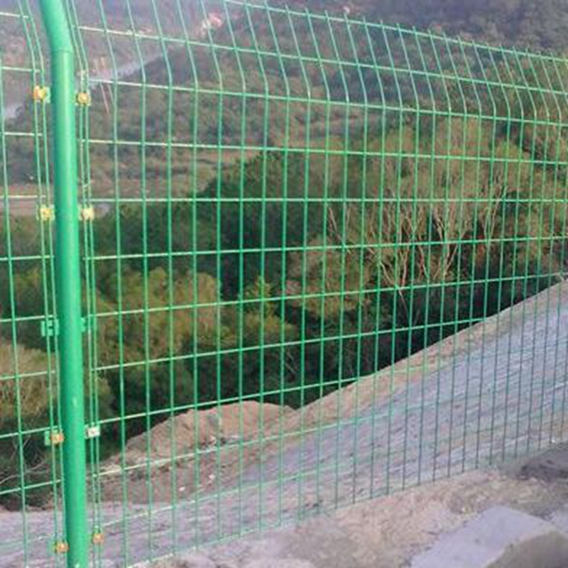
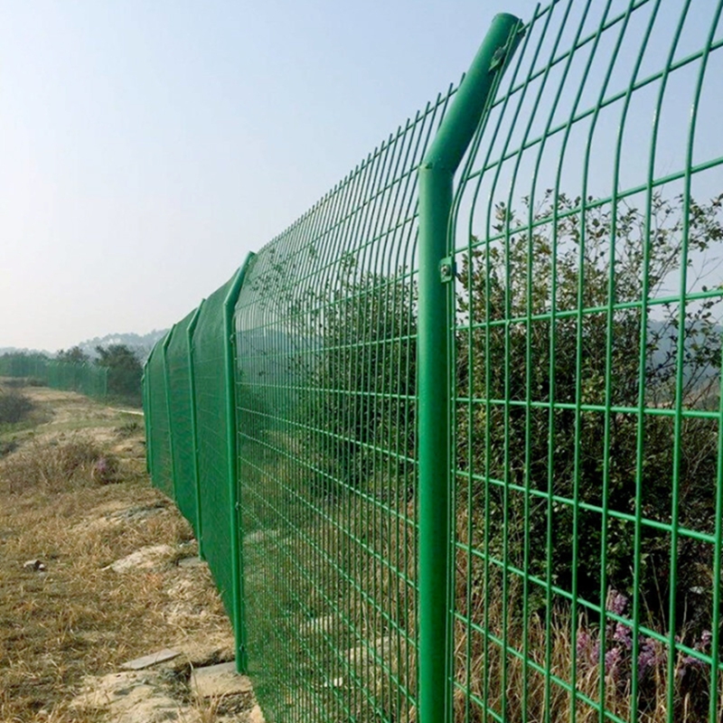
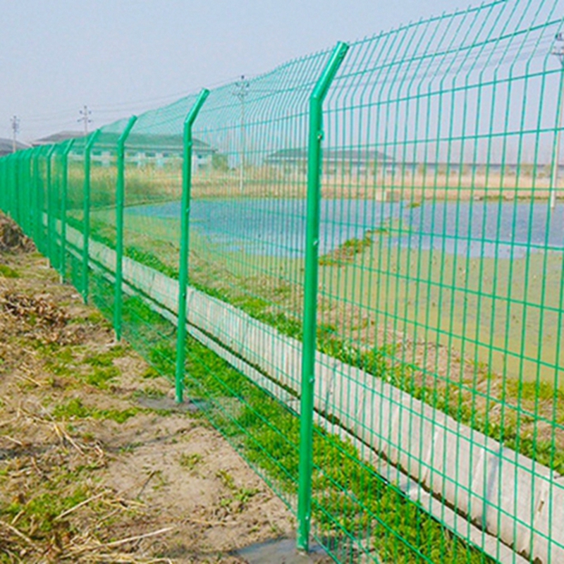
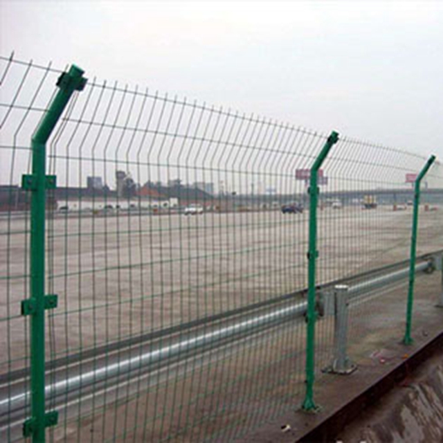
Double Wire Fence is also called Double Wire Mesh Fence, which can be surface treated as Galvanized Double Wire Mesh and Powder Coating Double Wire Mesh.
The structure of the double wire fence is simple, and the material is less. Usually, the raw material is low-carbon steel wire, which is made of low-carbon steel wire after welding, and the mesh is rectangular.
Double Wire Fence,Double Wire Mesh Fence,Galvanized Double Wire Mesh,Powder Coating Double Wire Mesh Anping County Dongjie Wiremesh Products Co., Ltd. , https://www.dongjiewire.com
The surface of the product can be galvanized or dipped in anti-corrosion treatment, and the bottom of the fence is integrated with the brick-concrete wall. This is for the rigidity of the mesh. Generally speaking, the service life can reach more than 10 years.
According to different use environments, the surface treatment of the mesh fence is also different. You can tell us your use environment, and Dongjie Wire Mesh's professional technical team will make a suitable recommendation for you.
