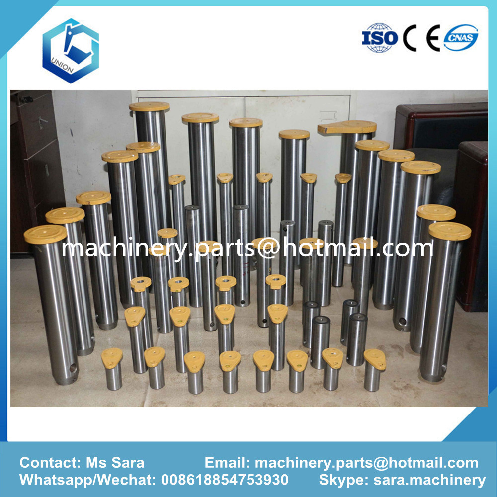
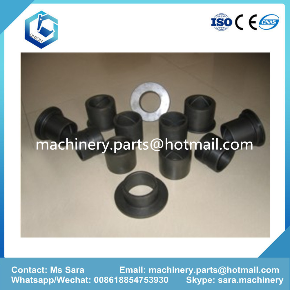
Excavator Bushing and Pin is maily used on arm cylinder , boom cylinder , bucket and link Etc.
Our material and tecnique is same with original.
1. Using 20CrMo steel as raw materials, which are provided by domestic famous manufacturer;
forging again and again to make forming, to make internal organization more tight, and increase
products` wear-resistance.
2. Using advanced CNC machine in strict accordance with products` technical requirement to
manufacture and ensure each position`s size which convenient to equip.
3. Having 13 years international advanced heat treatment technology, using carburization treatment on
them, guarantees their surface`s thickness of carburized layer and hardness; meanwhile good core .
We are speicialize in the bushing and pin for komatsu Excavator and loader.
The main model are : PC50MR-2, PC56-7, PC60-5, PC60-7, PC60-8, PC70-8, PC110-7/-8,
PC130-7/-8, PC160-7, PC200-7, PC200-8, PC220-7, PC220-8, PC270-7,
PC200-8EO, PC300-7, 360-7, PC400-6, PC400-7, WA470-3, PC450-8, D85PX-15,
PC650-8, WA500-6, D275AX-5, D575A-3, WA380-3, WA420-3, WA600-3,
D375A-5.
Excavator Pins,Excavator Bushing,Excavator Bucket Link Bushing,PC200-7 Excavator Bucket Link Bushing,PC200-8 Excavator Bucket Link Bushing JINING UNION MACHINERY AND PARTS CO., LTD. , https://www.vmpmachineryparts.com
Valve positioner; Retrofit; Damaged feedback circuit board I. Overview An increase in the production and demand of steel, resulting in the production of gas and gas media along with product production in large steel producers, such as those generated during the ironworks The gas mesons also tend to high temperature, high pressure, large air volume and so on. After decontamination purification system to purify the pipe network, a large part of pipe network gas generator can be converted into electrical energy production and reuse, and finally cleaned into the gas pipe network, medium-sized TRT generator unit is one of the important production processes, TRT generator saves energy consumption, protect the environment, build a resource-saving, reduce the cost of steel production, its safe and reliable operation of steel production has played a decisive role. Generating electricity using TRT technology and equipment also generates additional project benefits.
Second, the TRT process introduction Blast gas produced by the gas through the gas than the Beckhoff scrubber cleaning, through the entrance to start the butterfly valve , inlet flapper valve , rapid shut-off valve, into the TRT turbine expansion work done, was driven TRT turbine Drive the generator to generate electricity. Gas after doing work through the outlet flapper valve, electric butterfly valve exports into the net gas low pressure pipe network. In front of the entrance to start the valve, turbine outlet in parallel with the three groups of quick opening valve bypass. When the TRT is in the normal shutdown and the emergency shutdown occurs, the inlet fast-acting valve is cut off rapidly. The three groups of bypass are opened rapidly and the gas is quickly opened to bypass the low-pressure gas pipe network.
Third, the TRT components TRT The entire system consists of turbine host, a large valve system, high and low voltage power distribution system, water supply and drainage systems, lubricating oil system, power oil system, nitrogen seal system, hydraulic servo control system and automatic control system.
Fourth, the role of intelligent electric valve positioner in the TRT Instrument control to the drainage system, the valve positioner is an important part. Due to the large amount of drainage water from condensing the gas in the TRT pipeline, drainage is produced in the industrial new water to prevent the stagnation of the turbine vanes from being continuously or intermittently sprayed and cooled and cleaned against the vanes (that is, the discharge water before the turbine and the interstage water between the turbines Tank), so the need for pneumatic control valve to adjust the level of drainage regulation. Which in the 5 # TRT original pole between the drain valve positioner (YT-1000LS + PTM type) in use often appear many different symptoms. After analysis and research to confirm that the valve retainer has some design defects and quality problems, in order to ensure the normal operation of the TRT turbine generator vane sprayer drainage system, I modified the valve retainer and achieved good results.
5, 5 # TRT level valve positioner problems and impact (1) random spare parts valve positioner expired, frequent failures, can not purchase the original spare parts.
(2) often there is no reason for the power outage, resulting in control valve out of control, you must restart after power failure to return to normal. Check the control panel components wiring connection is solid, check the signal shielding ground, check the device itself grounded, the above checks are normal, unable to detect power outages.
(3) valve positioner without instructions, problems can not be reset debugging.
(4) valve potentiometer often appear no feedback signal display, resulting in instability of the water tank level control, the system can not be automatically adjusted.
(5) Valve positioner gas outlet often appear uncontrolled phenomenon, resulting in control valve out of control. Which found that some of the piezoelectric valve in the ambient temperature is lower than -15 ℃, it will produce non-action phenomenon, the inspection and verification of the switching amplifier in the piezoelectric valve failure caused by the valve positioner at -30 ℃ field environment Under the basic technical standards can not meet the requirements, but also simply can not meet the requirements of the region's temperature conditions.
(6) valve positioner control level water level tank water level control valve out of control, the water level is too high, easy to make the water into the turbine caused vane damage, while easily lead to gas pressure fluctuations directly affect the turbine inlet pressure , Seriously affect the blast furnace top pressure. When the water level is too low, gas leakage will easily lead to personnel poisoning.
Sixth, the transformation of intelligent electrical valve positioner Valve positioner evolved from the electrical converter evolved from the electrical converter on the basis of the feedback lever added to the valve positioner, making itself a closed-loop system. Also developed from the analog valve positioner to intelligent valve positioner, 5 # TRT generator now uses the old model of intelligent positioner, 6 #, 7 # TRT generator sets are selected new Siemens valve positioner. The operating principle of the SIPART PS2 smart electric valve positioner is completely different from the traditional positioner. The microprocessor compares the setpoint and position feedback. If the microprocessor detects a deviation, it uses a five-step switching program to control the piezo-electric valve, which in turn regulates the flow of air into the actuator's air chamber. The piezo valve converts the control commands into pneumatic displacement increments, when the control deviation is large (high speed zone). The positioner outputs a continuous signal. When the control deviation is not large (low speed zone), the positioner output pulse is continuous. When the controller deviation is small (adaptive or adjustable dead zone state), there is no control command output.
The role of the valve positioner is to accept the PLC 4-20mA current signal to drive the control valve action and the use of stem displacement feedback, the displacement signal directly compared with the valve position to improve stem linearity to overcome the stem A variety of additional friction, the media to be adjusted to eliminate the unbalanced force generated by the valve, so that the valve corresponds to the PLC to the 4-20mA current signal to achieve the correct positioning.
VII, the implementation of valve positioner retrofit steps and debugging 1. Valve positioner retrofitting steps to record the original valve positioner parameters: control mode, the direction of the switch, the direction of action, with or without alarm settings and valve characteristics.
To make a suitable mounting bracket, first select a suitable pad to solve the problem of inconsistent installation of the two valve positioners. Because the original valve positioner than the Siemens valve positioner, so the valve positioner pad higher.
According to the requirements of the choice of fixed: fixed plate or rod fixed, whether the need for pad processing, the use of used scaffolding, so that before and after the fixed bracket size, in order to solve the problem of asymmetric pitch. Construction of the most complex is the new valve positioner connecting rod fixed, the original valve positioner link with the existing valve positioner does not match the abandoned locator connecting rod on the transformation, the former locator on the connecting rod , With locking function can also adjust the length. However, due to the small hole in the original connecting rod, it needs to be expanded from a new drilling hole, break it again and make it reach the required length, and then handle it with the locking screw so that it can be connected with the actuator.
2. Valve Positioner Modification Power-on Debug Before power-on, input the 4-20 mA signal source connected to terminals 6 and 7 (6 +, 7-). After power-on, the positioner will display NOINI Did not download the program. The valve positioner has a yellow cuboid above and below it to manually adjust it. Adjustable angle of (33% / 90%) that use a screwdriver 33% or 90%. If the valve stroke is small, the yellow cuboid adjusted to the bottom, the adjustable angle of 33%; if the valve stroke is large, the rectangular parallels transferred to the top, the adjustable angle of 90%. It is also possible to open the valve to 50% of the actual position and adjust the gear (ie potentiometer) on the underside of the positioner to the same 50% position (screen display). Press the small valve positioner button for more than 5 seconds to enter the menu settings. Then press the small key to enter the first setting item YFCT select the type of actuator, select the end, then press the small hand key to enter the second YAGL setting item, select the adjustable angle, with the plus and minus keys to adjust the same as above into the fourth INITA automatic calibration, press the plus button for more than 5 seconds to enter the automatic calibration phase, FINSH appears after the completion of the screen shows that the automatic calibration is completed.
references:
[1] Jia Qian. Instrumentation Manual. Chemical Industry Press, 2004-1.
[2] Siemens Valve Positioner Operating Manual. Siemens AG (supplied), 2012-7.
[3] Control Plant Liu Zhiqin Master Workstation Courseware Author:
Liu Qinyuan (1979-), male, Benxi City, Liaoning Province, automation instrumentation senior engineer, college, Bengang control plant, mainly engaged in gas plant instrumentation maintenance.


Abstract: This paper introduces the technological process and system components of 5 # TRT of Benxi Iron and Steel Co., Ltd. In view of the problems and shortcomings in the recent operation of the valve positioner of the water supply and drainage system, the TRT liquid level valve positioner has been modified to meet Production needs, achieved the desired results.